
Image to Robot Drawing Trajectory Converter
This page is based on the following resources:
Paper
Code
Introduction
This project was a part of the robot drawing project using a differential wheeled robot for iRobot Inter Hackathon. The robot was equipped with drawing materials and its purpose was to draw objects in reference images. The images were provided either directly from users or from the robot’s fisheye camera which required undistortion. Performing Canny Edge Detection, outlines of the objects in the images were detected and trajectories that the robot should follow while drawing or not drawing were computed connecting the outlines based on closest pixel search. If two outline pixels were far from a certain threshold distance, it was considered as non-drawing area. An additional cascade classifier was used as well in order to detect human faces in the input images and produce better outline results.
Test Images
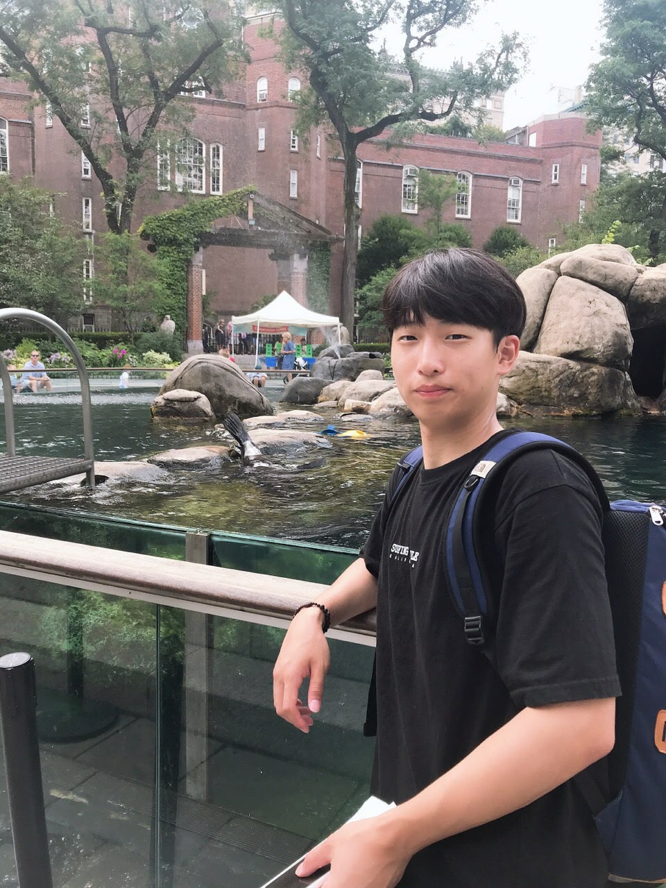
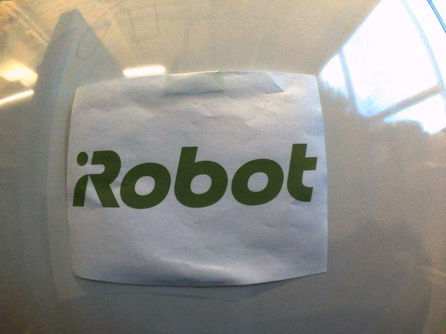
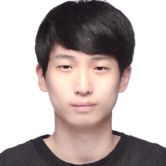
Fig. 1: Profile image and fisheye camera image for testing.
The images in Fig. 1 were tested to produce drawing trajectories for the user input image and robot’s fisheye camera image respectively. For the fisheye camera image, it had to be undistorted first so that the resulting trajectory didn’t look different than the actual object. Also, only the desired objects (the human face and logo) in the images needed to be converted to the trajectories. More tested images and results can be found in Appendix A.
Image Undistortion
The camera image in Fig. 1 had a barrel distortion. This could be simply undistorted using the camera’s intrinsic parameters and distortion coefficients. The parameters and coefficients were provided in advance so camera calibration was not necessary. Detailed procedures for the undistortion can be found in this repo. The resulting undistorted image is shown in Fig. 2 below.
Fig. 2: Undistorted fisheye camera image.
Object Outline Detection
The input images were blurred using a Gaussian kernel to reduce noises and Canny Edge Detection was performed to compute outlines of the objects in the images. For the profile image, a ROI had to be defined to target only the face unless undesired outlines of the background were computed. The ROI was detected using a cascade classifier model in OpenCV was used. The classifier model was effective in detecting frontal faces. The resulting ROI of the profile image is shown in Fig. 3 below.

Fig. 3: ROI of the profile image detected by the cascade classifier.
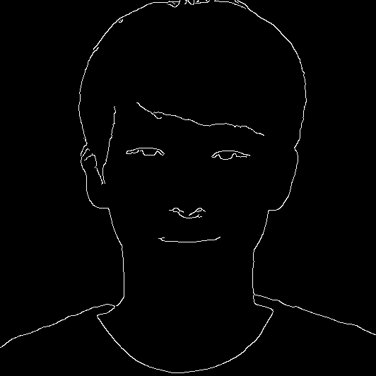
The resulting outlines of the input images are shown in Fig. 4 below.
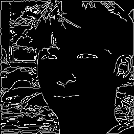
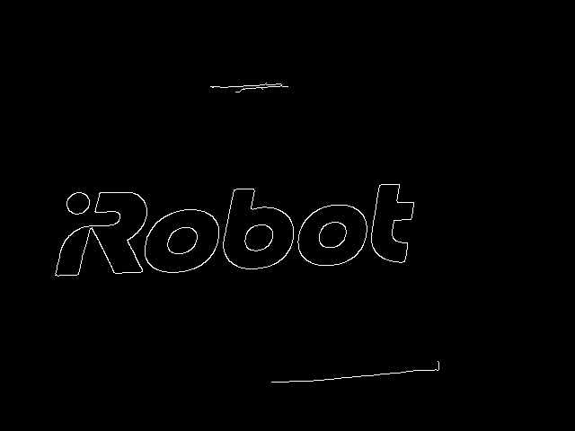
Fig. 4: Outlines detected by Canny Edge Detection.
Even though the profile image was cropped based on the ROI, there were still some unwanted edges detected from the background. This could be improved by applying filtering methods (erosion and dilation) and tuning the paramters of Canny Edge Detection. Detailed procedures for the ROI and outline detections can be found in this repo.
Path Planning and Trajectory Results
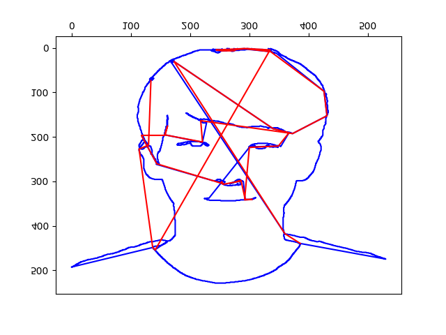
The edges detected were searched through to plan drawing paths. Starting from a edge pixel, its closest edge pixel was searched and connected. If the two pixels were in a specified threshold distance, the connection was considered as a non-drawing area. The resulting drawing trajectories are shown in Fig. 5 below.
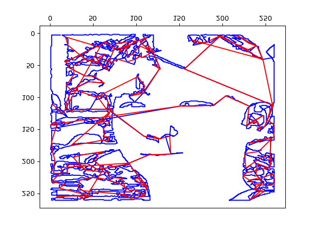
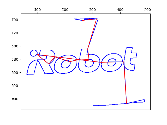
Fig. 5: Drawing trajectories of the input images.
In Fig. 5, blue lines indicated that the robot should draw while following the paths and red lines indicated that the robot should not draw while following the paths. Detailed procedures for the drawing path planning can be found in this repo.
Appendix A: More Testing Images and Results
Other profile and logo images were tested additionally and demonstrated the performance of the trajectory converter.
![]()
![]()
![]()